
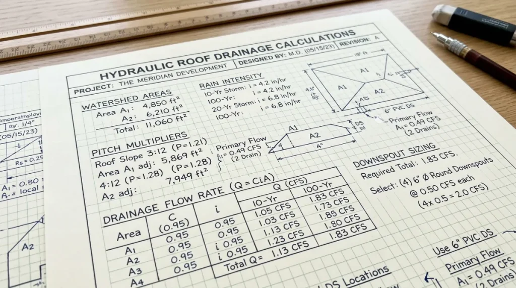
Introduction to Hydraulic Roof Drainage
A residential or commercial guttering system is not a passive architectural feature. It is a hydraulic conveyance structure engineered to collect, transport, and discharge a calculated volume of stormwater away from the building envelope within a defined time window — specifically, the peak intensity window of a design storm event.
When that conveyance structure is undersized, incorrectly pitched, or specified without reference to regional precipitation data, the consequences are mechanical and structural. Overflow at the fascia line saturates the soffit and roof deck. Discharge concentrated at the foundation perimeter drives hydrostatic pressure against the footing. Over multiple storm cycles, those failure mechanisms produce rot, mold, foundation cracking, and interior water intrusion.
Gutter sizing calculation standards exist precisely to prevent that category of failure at the specification stage — before a single hanger is driven into a fascia board. The calculations documented in this reference establish the mathematical relationship between three primary variables: the structural watershed area of the roof, the regional precipitation intensity for the design storm event, and the hydraulic cross-sectional capacity of the selected gutter profile. All three variables must be resolved correctly for the drainage system to perform as specified.
The Core Gutter Sizing Formula: SMACNA Guidelines
The Sheet Metal and Air Conditioning Contractors’ National Association (SMACNA) publishes the industry-standard hydraulic sizing formula for residential and commercial roof drainage systems. This formula is the baseline calculation used by licensed contractors, architects, and building officials to verify that a proposed guttering system can handle the peak runoff load generated by the local design storm event.
The SMACNA runoff formula is expressed as follows:
$$Q = \frac{A \times I}{43,200}$$
Each variable in this equation carries a precise technical definition. Substituting approximations or nominal values for any variable introduces cumulative error that compounds across the full drainage system specification.
- Q — Runoff Flow Rate: The calculated peak stormwater runoff volume expressed in cubic feet per second (CFS). This is the output value the formula produces — the volume of water the guttering system must be capable of moving during the peak intensity window of the design storm.
- A — Adjusted Design Roof Area: The effective watershed area of the roof surface expressed in square feet. This is not the footprint area of the building. It is the true projected horizontal area of each roof plane draining to a given gutter run, adjusted by the applicable pitch multiplier factor documented in Section 3 of this reference.
- I — Precipitation Intensity: The regional rainfall intensity expressed in inches per hour, drawn from the 100-year, 5-minute recurrence interval for the project location. This value is not an annual average rainfall figure. It is the peak intensity value from the statistically derived design storm — the event the drainage system must be sized to handle without overflow. Regional intensity values are published in NOAA Atlas 14 and referenced in applicable IRC and IBC code tables.
- 43,200 — Unit Conversion Constant: This constant converts the product of square feet and inches per hour into cubic feet per second, maintaining dimensional consistency across the equation. It is a fixed mathematical constant, not a variable.
Once Q is established in CFS, that value is cross-referenced against the flow capacity of the selected gutter profile at the specified pitch to confirm the trough cross-section is sufficient to carry the calculated peak load without surcharging.
Roof Pitch Adjustment Factors: Watershed Multipliers
A steeply pitched roof does not behave identically to a low-slope roof under the same rainfall event. Steep roof planes intercept wind-driven rain at an angle that increases the effective collection area beyond the true horizontal projection. They also accelerate water velocity down the roof surface, compressing the time window in which the full runoff volume arrives at the gutter trough.
Both effects — increased effective collection area and accelerated delivery velocity — increase the hydraulic demand on the guttering system relative to what the raw horizontal footprint calculation would suggest. Pitch multiplier factors correct for this by scaling the design roof area (A) upward before it enters the SMACNA formula.
The following pitch multiplier table reflects the adjustment factors applied to the horizontal projected roof area by slope category:
| Roof Pitch Range | Slope Classification | Watershed Multiplier |
|---|---|---|
| Flat to 3:12 | Low slope | 1.00 |
| 4:12 to 5:12 | Moderate slope | 1.05 |
| 6:12 to 8:12 | Standard residential slope | 1.10 |
| 9:12 to 11:12 | Steep residential slope | 1.20 |
| 12:12 or steeper | High-pitch / architectural | 1.30 |
Application note: A 1,000 square foot roof plane measured as a horizontal projection at a 9:12 pitch carries an adjusted design area of 1,200 square feet for calculation purposes. That 20% area increase directly scales the Q output and must be reflected in the final gutter profile and downspout sizing. Omitting the pitch multiplier on steep-slope residential work is one of the most consistent sources of chronic overflow failure on otherwise correctly installed systems.
Gutter Profile Cross-Sectional Capacities
The SMACNA formula produces a required flow rate in CFS. The selected gutter profile must provide sufficient cross-sectional area — at the specified installation pitch — to carry that flow rate without surcharging the trough above its design fill line.
Three profile categories cover the majority of residential and light commercial guttering specifications:
- 5-Inch K-Style (Standard Residential): Cross-sectional area of approximately 7.96 square inches. Estimated flow capacity at 1/16-inch-per-foot pitch is 63 GPM (0.14 CFS). Correct specification for standard residential rooflines with moderate watershed areas up to approximately 5,500 square feet per outlet under average regional intensity conditions. The flat-bottom profile mounts flush to standard fascia depth without projection.
- 6-Inch K-Style (Large Residential / Light Commercial): Cross-sectional area of approximately 11.77 square inches. Estimated flow capacity at 1/16-inch-per-foot pitch is 102 GPM (0.23 CFS). Required specification for rooflines with watershed areas exceeding 5,500 square feet per outlet, valley-concentrated discharge points, or regional intensity values above 4.0 inches per hour. The 6-inch K-style is the minimum correct specification for most southeastern U.S. residential production work.
- Box Gutter Profile (Commercial / High-Load): Cross-sectional area varies by fabricated dimension — commonly specified from 16 to 32+ square inches depending on the design load. Box gutters are field-fabricated or custom-roll-formed to meet a calculated CFS requirement rather than selected from a nominal size chart. They are the correct specification for commercial rooflines, large multi-valley residential structures, and any application where K-style nominal sizing cannot meet the calculated Q value at a physically practical installation pitch.
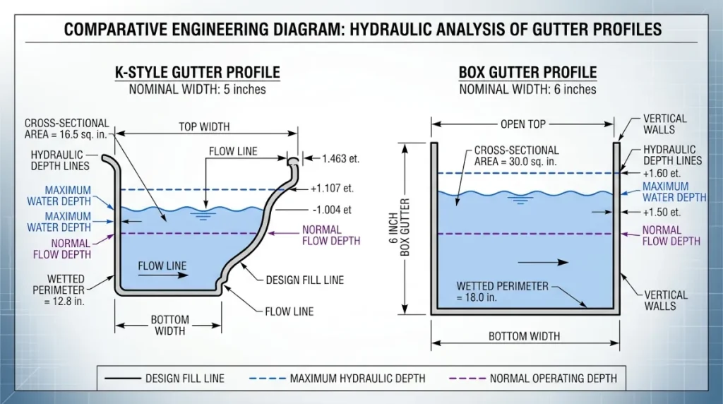
Critical specification note: Cross-sectional area figures represent maximum theoretical capacity at full trough fill. Operational design practice sizes the trough to carry the calculated peak Q at no more than 85% of full cross-sectional capacity — leaving a 15% hydraulic headroom buffer for debris accumulation, joint friction loss, and rainfall events that marginally exceed the design storm parameters.
Downspout Placement and Escapement Math
A correctly sized gutter trough that feeds an undersized or incorrectly spaced downspout system will still overflow. The downspout is the escapement point of the hydraulic system — the outlet through which all collected volume must exit the trough and enter the discharge run. Its sizing and placement are independent calculations from the trough profile selection.
Downspout Cross-Section Sizing Standard
The baseline plumbing code standard for residential downspout sizing is 1 square inch of downspout cross-sectional area per 1,200 square feet of adjusted roof area under a 1-inch-per-hour rainfall intensity baseline. That ratio scales linearly with regional intensity — a location with a design storm intensity of 4.8 inches per hour requires proportionally more downspout cross-section per equivalent roof area than a location at 1.0 inches per hour.
Standard residential downspout sizes and their corresponding cross-sectional areas are as follows:
- 2-inch round downspout: 3.14 square inches — adequate for small isolated roof sections only
- 3-inch round downspout: 7.07 square inches — standard minimum for most residential outlet points
- 2×3-inch rectangular downspout: 6.00 square inches — common residential profile, equivalent to approximately 3-inch round capacity
- 3×4-inch rectangular downspout: 12.00 square inches — correct specification for high-load outlet points, valley discharge, or southeastern U.S. regional intensity zones above 4.0 inches per hour
The 50-Foot Maximum Gutter Run Constraint
Gutter runs exceeding 50 linear feet require an expansion joint or a dual-outlet configuration to manage thermal expansion safely. Aluminum expands and contracts at approximately 0.0000128 inches per inch per degree Fahrenheit. On a 60-foot aluminum run experiencing a 100°F seasonal temperature swing — a routine condition across most of the continental United States — that produces over 0.9 inches of linear movement.
Without a designed expansion point, that movement is absorbed by the end caps, outlet connections, and hanger fasteners — producing joint failure, sealant cracking, and eventual trough separation at the weakest connection point in the run. The 50-foot constraint is not a conservative approximation. It is the maximum run length at which thermal movement remains within the tolerance of standard sealant and fastener connections without a dedicated expansion joint.
Runs exceeding 50 feet must be configured as either a dual-outlet run — with a high-point center and outlets at both ends — or a single-outlet run with a fabricated expansion joint placed at the appropriate interval to absorb thermal movement without transferring stress to fixed connection points.
Applying These Standards in the Field
The calculation framework documented in this reference — SMACNA runoff formula, pitch-adjusted watershed areas, profile cross-sectional capacities, and downspout escapement math — represents the complete engineering baseline for a correctly specified residential or commercial guttering system. These are not theoretical parameters. They are the exact figures that separate a drainage system designed to perform from one that generates service calls, warranty claims, and structural damage within the first five years of installation.
Every figure in this reference reflects gutter sizing calculation standards verified against real installation outcomes across 31 years of production-scale residential and commercial drainage work. No formula has been included that has not been stress-tested against the conditions that cause guttering systems to fail — and no specification shortcut has been documented that the field record does not consistently penalize.