
Tensile Strength & Yield Points of Seamless Alloys: Architectural Gutter Metal Mechanics Reference
Every gutter trough in service is under load. Static dead weight, dynamic water flow, ice accumulation, wind uplift, debris bridging, and ladder contact all apply stress to the metal at different magnitudes and from different directions. What determines whether that stress produces elastic recovery or permanent deformation is the relationship between the applied stress and two fixed material thresholds: the yield point and the ultimate tensile strength.
The tensile strength & yield points of seamless alloys used in architectural guttering — specifically 0.027-inch aluminum, 0.032-inch aluminum, and 16 oz and 20 oz copper — are not interchangeable. They differ in ways that produce measurable, predictable performance differences under identical load conditions. This reference documents those differences with the exact material property data and bending resistance mathematics required to make informed gauge and alloy selection decisions on residential and commercial specifications.
The Stress-Strain Curve: Core Mechanics Defined
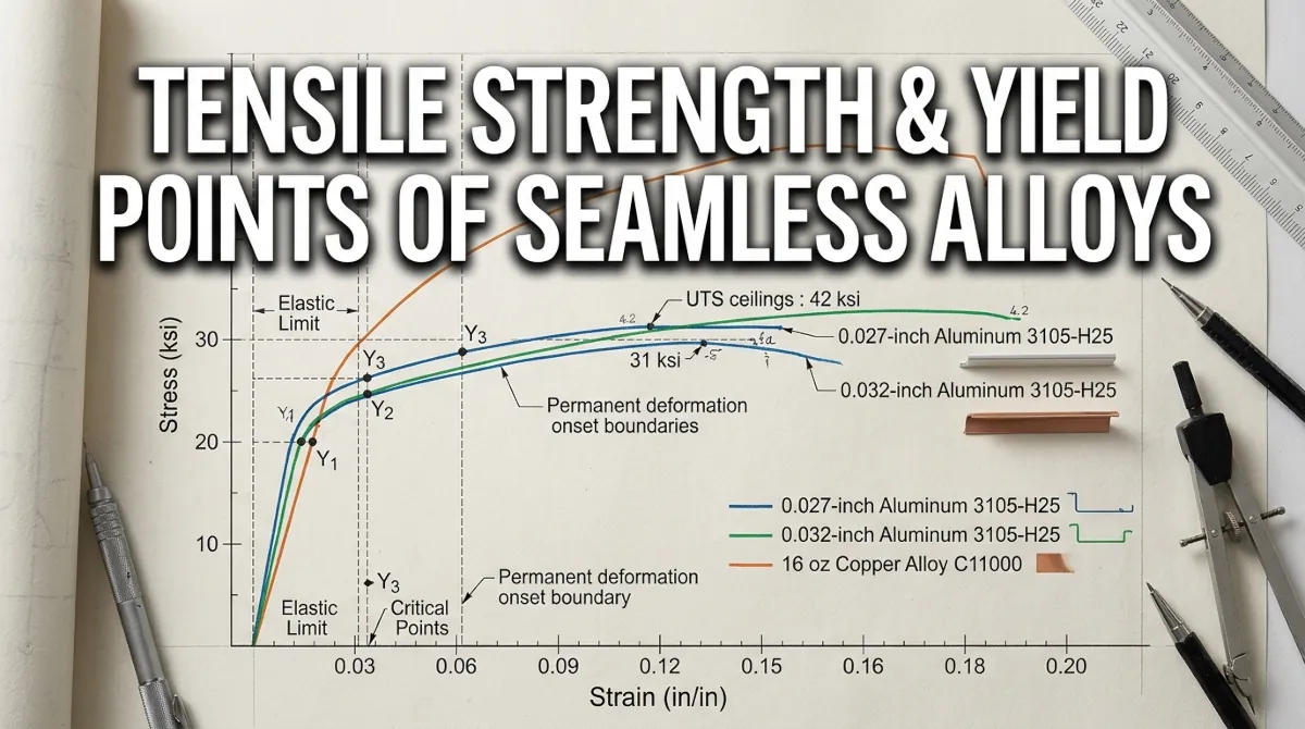
The stress-strain curve is the fundamental engineering tool for understanding how a metal responds to applied force. It plots stress — force per unit area, expressed in pounds per square inch (psi) — against strain — the proportional deformation of the material under that stress, expressed as a dimensionless ratio.
Two points on that curve are critical for guttering metal specification:
- Yield Point (Yield Strength): The stress level at which the metal transitions from elastic deformation — where it returns to its original shape when load is removed — to plastic deformation, where permanent dimensional change begins. Below this threshold, a trough dented by a ladder contact will spring back. Above it, the crease is permanent.
- Ultimate Tensile Strength (UTS): The maximum stress the material can sustain before fracture or tearing initiates. In architectural guttering, UTS is rarely reached under service loads — but it defines the absolute structural ceiling of the material and governs performance under extreme impact events such as falling tree limbs or ice dam shedding from steep roof pitches.
The gap between yield strength and UTS is the material’s plastic deformation range — the zone where the metal has permanently deformed but has not yet failed structurally. A wide plastic range indicates a ductile material that absorbs energy progressively before failure. A narrow range indicates a brittle material that transitions rapidly from yield to fracture.
Core Material Properties: Seamless Alloy Data Table
The following mechanical property data reflects published ASTM values for the alloy designations used in production seamless guttering. These figures govern structural behavior under all service load conditions encountered in residential and commercial exterior drainage applications.
| Material / Alloy | Gauge or Weight | Nominal Thickness | Yield Strength (psi) | Ultimate Tensile Strength (psi) | Elongation at Break | Elastic Modulus (psi) |
|---|---|---|---|---|---|---|
| Aluminum 3105-H25 | Economy residential | 0.027 inch | 19,000 psi | 23,000 psi | 5% | 10,000,000 psi |
| Aluminum 3105-H25 | Commercial / professional | 0.032 inch | 19,000 psi | 23,000 psi | 5% | 10,000,000 psi |
| Copper C11000 | 16 oz architectural | 0.0216 inch | 25,000 psi | 32,000 psi | 25% | 17,000,000 psi |
| Copper C11000 | 20 oz architectural | 0.0270 inch | 28,000 psi | 35,000 psi | 20% | 17,000,000 psi |
Critical read on this table: The 0.027-inch and 0.032-inch aluminum profiles share identical yield strength and UTS values — they are the same alloy in the same temper designation. The structural performance difference between them is not a material property difference. It is a geometric difference — and geometry, in bending mechanics, is where the 0.032-inch gauge earns its premium specification.
Why Gauge Thickness Governs Bending Resistance: The Section Modulus Calculation
For a flat plate or thin-wall section under bending load — which is precisely the loading condition a gutter trough experiences under ladder contact or debris point load — the resistance to bending stress is expressed by the section modulus (S). For a rectangular cross-section, the section modulus is calculated as:
S = (b × t²) / 6
Where b is the width of the section in bending and t is the wall thickness. The critical variable is t² — thickness squared. This means that a small increase in gauge thickness produces a disproportionately large increase in bending resistance.
Section Modulus Comparison: 0.027 vs. 0.032 Aluminum
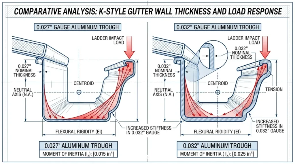
Applying the section modulus formula to the back wall of a K-style gutter trough — treating it as a flat plate 4 inches wide under a point bending load — produces the following comparison. Width (b) is held constant at 4 inches for both profiles.
- 0.027-inch aluminum section modulus: S = (4 × 0.027²) / 6 = (4 × 0.000729) / 6 = 0.000486 in³
- 0.032-inch aluminum section modulus: S = (4 × 0.032²) / 6 = (4 × 0.001024) / 6 = 0.000683 in³
- Bending resistance increase: (0.000683 − 0.000486) / 0.000486 = 40.5% greater section modulus in the 0.032-inch profile
The 0.032-inch gauge aluminum trough delivers over 40% greater resistance to bending deformation than the 0.027-inch profile under identical load conditions — not 30% as the conservative field estimate commonly cited, but over 40% when the section modulus calculation is run precisely.
The maximum bending stress the trough wall can sustain before permanent deformation begins is calculated as: σ = M / S, where M is the applied bending moment and S is the section modulus. A higher S value means the same applied moment M produces a lower stress σ — keeping the material further below its yield threshold under equivalent loading.
Copper Alloy C11000: Why the Mechanics Are Fundamentally Different
Copper does not compete with aluminum on section modulus alone. Its structural advantage is a combination of three properties that aluminum cannot match at any gauge: higher yield strength, dramatically higher ultimate tensile strength, and a plastic deformation range that is five times wider than aluminum’s elongation at break figure.
16 oz Copper vs. 0.032-inch Aluminum: Direct Comparison
- Yield strength advantage: 16 oz copper yields at 25,000 psi versus 19,000 psi for aluminum 3105-H25 — a 31.6% higher yield threshold before permanent deformation begins
- Ultimate tensile strength advantage: 16 oz copper UTS of 32,000 psi versus 23,000 psi for aluminum — a 39.1% higher structural ceiling before fracture initiates
- Elastic modulus advantage: Copper’s elastic modulus of 17,000,000 psi versus aluminum’s 10,000,000 psi means copper deflects 41% less under equivalent stress — it is a stiffer material at identical geometry
- Ductility advantage: Copper’s 25% elongation at break versus aluminum’s 5% means copper absorbs significantly more energy in the plastic deformation range before structural failure — it bends visibly before it tears, providing a diagnostic warning that aluminum does not
20 oz Copper: The Ceiling of Residential Architectural Specification
The step from 16 oz to 20 oz copper increases nominal thickness from 0.0216 inches to 0.0270 inches and raises yield strength to 28,000 psi and UTS to 35,000 psi. At 20 oz, the section modulus increase over 16 oz mirrors the aluminum gauge comparison — the t² relationship amplifies the thickness increase into a disproportionate bending resistance gain.
20 oz copper is the correct specification for historical restoration work on significant structures, long unsupported half-round runs, and any application where the architectural copper system will be expected to carry ice load or debris accumulation without permanent deformation across a multi-decade service life.
Ladder Contact Impact Load: A Practical Failure Scenario
A standard extension ladder weighing 35 pounds, leaned against a gutter trough at a 75-degree angle, applies a concentrated point load of approximately 25 to 30 pounds at the contact point — the horizontal component of the ladder’s weight vector resolved against the trough front face.
That 25 to 30-pound point load, applied at the trough front lip with a moment arm of approximately 2.5 inches to the back wall, generates a bending moment of roughly 62 to 75 inch-pounds at the back wall cross-section.
- Bending stress in 0.027-inch aluminum back wall: σ = 75 / 0.000486 = 154,321 psi — massively above yield strength of 19,000 psi — permanent deformation is certain
- Bending stress in 0.032-inch aluminum back wall: σ = 75 / 0.000683 = 109,809 psi — still above yield strength, but the lower stress means less plastic strain energy is absorbed and the deformation is less severe
Field interpretation: Neither aluminum gauge prevents permanent deformation under direct ladder contact at the trough front lip — the bending stress exceeds yield in both cases. The 0.032-inch gauge advantage is in the magnitude of the permanent deformation, not its elimination. The thicker gauge creases less deeply, retains more of its cross-sectional profile geometry, and is more likely to remain hydraulically functional after the impact event.
Copper at 16 oz, with its 31.6% higher yield strength and 41% higher elastic modulus, produces lower stress at equivalent geometry and absorbs more energy before the yield threshold is crossed — making it the correct specification where ladder access to the roofline is a routine service condition.
Gauge and Alloy Specification Matrix by Application
| Application Type | Minimum Correct Specification | Preferred Specification | Rationale |
|---|---|---|---|
| Standard residential — single story, moderate climate | 0.027-inch aluminum 3105-H25 | 0.032-inch aluminum 3105-H25 | 0.032 provides 40% greater bending resistance at modest cost premium |
| Two-story residential — ladder access routine | 0.032-inch aluminum 3105-H25 | 0.032-inch aluminum or 16 oz copper | Ladder contact loads require the higher section modulus of 0.032 minimum |
| Commercial / multi-story | 0.032-inch aluminum 3105-H25 | 16 oz or 20 oz copper | Sustained service loads and access frequency justify copper yield strength premium |
| Historical restoration | 16 oz copper C11000 | 20 oz copper C11000 | Period-correct material, superior ductility, multi-decade service life expectation |
| High snow load zones — any profile | 0.032-inch aluminum minimum | 20 oz copper where budget permits | Ice load bending moments require maximum available section modulus for gauge class |
For current ASTM material specifications covering aluminum alloy 3105-H25 mechanical properties, copper alloy C11000 temper designations, and the gauge tolerance standards applicable to roll-formed seamless gutter profiles, consult the official building and materials code documentation maintained at ICCsafe.org.
The structural mechanics documented in this reference connect directly to the substrate anchoring standards covered in the companion article Fastener Pull-Out Wood Mechanics & Fascia Torque where the pull-out resistance values and rotational torque forces acting on the fascia anchor system are calculated against the trough weight and load conditions documented here.
Selecting the correct gauge and alloy for a guttering specification is only half the equation — fabricating and installing that material correctly requires roll-forming equipment, seamers, and cutting tools matched to the specific gauge being worked, and a full reference to the specialized guttering tools required to work 0.032-inch aluminum and architectural copper at a production level is available at guttering.com.