
Drainage Slope Calculations: Pitch Thresholds on Extended Gutter Runs
Standard residential guttering references treat pitch as a single fixed value — typically cited as 1/16-inch of drop per linear foot — and move on. That treatment is adequate for a 30-foot run draining to a single outlet.
It is not adequate for a 50-foot run, a 60-foot commercial fascia, or any extended roofline where the cumulative effect of a continuous single-direction slope forces the low end of the gutter trough below the structural fascia board line.
Drainage slope calculations on extended runs are not a matter of selecting a pitch and applying it uniformly — they are a matter of calculating exactly where each pitch standard breaks down structurally, and specifying the correct layout configuration before that threshold is crossed.
This reference documents the exact pitch formulas, cumulative drop figures, and layout pivot points required to make that determination correctly on any run length encountered in residential or light commercial guttering work.
The Three Operational Pitch Standards: Definitions and Field Application
Three pitch standards cover the full range of residential and commercial guttering specifications. Each produces a different cumulative drop profile across an extended run, and each has a defined application envelope where it is the correct specification.
1/16-Inch Drop Per Linear Foot — Minimum Functional Pitch
The 1/16-inch standard is the minimum pitch at which water moves reliably through an aluminum or copper gutter trough under normal flow conditions. It is the correct specification for standard residential runs of 40 feet or less where fascia board geometry, roofline aesthetics, or hanger elevation constraints limit the available drop.
Below this threshold, water velocity is insufficient to self-clear debris accumulation and standing water develops at low points — accelerating sealant degradation and trough corrosion at joint locations.
- Drop per foot: 0.0625 inches
- Cumulative drop at 30 feet: 1.875 inches
- Cumulative drop at 40 feet: 2.50 inches
- Cumulative drop at 50 feet: 3.125 inches
- Cumulative drop at 60 feet: 3.75 inches
1/8-Inch Drop Per Linear Foot — Standard Production Pitch
The 1/8-inch standard is the production baseline used by most experienced residential guttering crews on runs between 20 and 50 feet. It provides measurable flow velocity improvement over the minimum pitch standard, clears debris more effectively under low-flow conditions, and remains within the visible aesthetic tolerance of most fascia board profiles up to approximately 40 feet of single-direction run.
- Drop per foot: 0.125 inches
- Cumulative drop at 30 feet: 3.75 inches
- Cumulative drop at 40 feet: 5.00 inches
- Cumulative drop at 50 feet: 6.25 inches
- Cumulative drop at 60 feet: 7.50 inches
1/4-Inch Drop Per Linear Foot — High-Flow Pitch
The 1/4-inch standard is applied on short, high-load runs — valley discharge points, heavily shaded debris-prone sections, or commercial downspout approaches where maximizing flow velocity through a constrained run length is the primary specification objective. On extended runs, this pitch standard crosses structural fascia limits rapidly and is almost never the correct specification for a continuous single-direction layout exceeding 25 feet.
- Drop per foot: 0.250 inches
- Cumulative drop at 20 feet: 5.00 inches
- Cumulative drop at 30 feet: 7.50 inches
- Cumulative drop at 40 feet: 10.00 inches
- Cumulative drop at 50 feet: 12.50 inches
The Structural Fascia Constraint: Where Pitch Becomes a Layout Problem
Every pitch calculation operates against a fixed physical constraint: the depth of the fascia board. Standard residential fascia boards are nominally 1×6 lumber — actual face depth of 5.5 inches. Wider fascia profiles at 1×8 provide 7.25 inches of face depth.
The gutter hanger at the high end of the run is typically set with the back of the trough flush to the top of the fascia board, leaving the full fascia face depth as the available drop budget before the low-end hanger exits the bottom of the fascia board entirely.
Once the cumulative drop of the selected pitch exceeds the available fascia depth, the low-end hanger has no structural substrate to fasten to. The trough drops below the fascia line, the roofline aesthetic is compromised, and — more critically — the structural attachment of the low-end run is no longer anchored to a solid backing. This is the exact threshold where a continuous single-direction layout must be replaced with a center-high, dual-outlet split configuration.
The following table documents the precise run lengths at which each pitch standard exhausts a standard 5.5-inch fascia depth budget:
| Pitch Standard | Drop Per Foot | Max Single-Direction Run (5.5-inch fascia) | Max Single-Direction Run (7.25-inch fascia) |
|---|---|---|---|
| 1/16 inch/ft | 0.0625 in | 88 linear feet | 116 linear feet |
| 1/8 inch/ft | 0.125 in | 44 linear feet | 58 linear feet |
| 1/4 inch/ft | 0.250 in | 22 linear feet | 29 linear feet |
Field application note: These figures represent the absolute structural maximum — the point at which the trough physically exits the fascia board. Practical layout practice sets the layout pivot point earlier, maintaining a minimum 1-inch clearance buffer above the bottom fascia edge at the low-end hanger. Apply that buffer by subtracting 1 inch from the available fascia depth before calculating the maximum single-direction run length for the selected pitch.
The Dual-Outlet Center-High Split Layout: When and How to Specify It
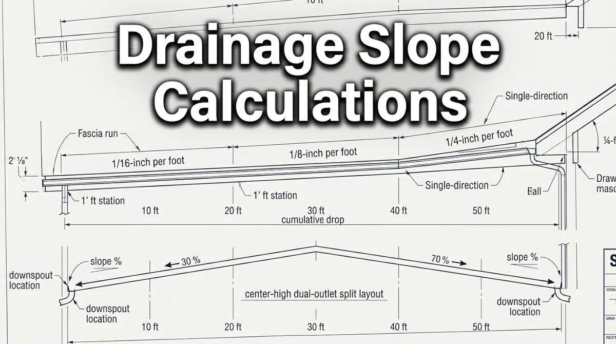
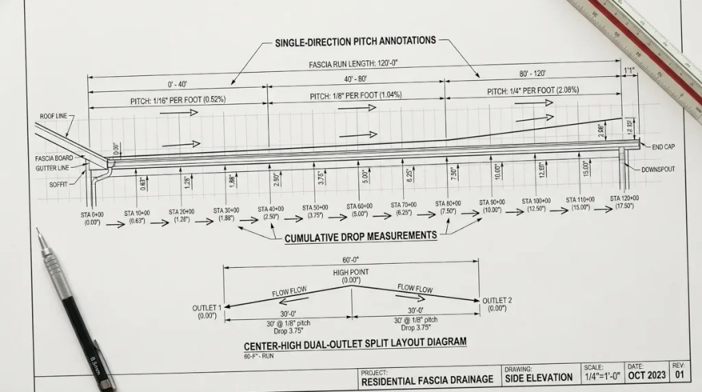
When a roofline run exceeds the single-direction threshold for the required pitch standard, the correct specification is a center-high, dual-outlet split layout. In this configuration, the high point of the run is established at the center of the fascia span. The trough pitches downward in both directions from that center point, terminating at outlets positioned at each end of the run. Each half of the run is treated as an independent hydraulic section for pitch calculation and outlet sizing purposes.
Layout Math for the Center-High Split
The center-high split effectively halves the active run length for pitch calculation purposes. A 60-foot fascia run configured as a center-high dual-outlet split produces two 30-foot sections, each pitching independently to its respective outlet. At the 1/8-inch pitch standard, each 30-foot section generates a cumulative drop of 3.75 inches — well within the 5.5-inch fascia depth budget and maintaining the 1-inch clearance buffer with margin to spare.
- Total run length: 60 feet
- Active section length per outlet: 30 feet
- Pitch standard: 1/8 inch per foot
- Cumulative drop per section: 3.75 inches
- Fascia depth consumed: 3.75 of 5.5 inches available — 1.75-inch clearance buffer maintained
- Outlets required: 2 — one at each end of the run
- Downspout runs required: 2 — sized independently per outlet drainage load
Outlet Sizing in a Split Layout
Each outlet in a dual-outlet split layout serves half the total roof watershed area of the run. Downspout sizing for each outlet is calculated against that half-watershed figure — not the total run watershed.
This distinction matters on high-intensity regional installations where the temptation to upsize a single central outlet rather than run two downspouts introduces a hydraulic bottleneck that the split layout geometry cannot resolve. Two correctly sized outlets at the run ends will always outperform one oversized central outlet on a split-pitch configuration.
For the current IRC and IBC code references governing minimum slope requirements and downspout placement standards applicable to residential and light commercial drainage system design, consult the official building code documentation maintained at ICCsafe.org.
Cumulative Error: Why “Standard Pitch” Is Not a Safe Default
The failure pattern that makes extended-run pitch calculations a diagnostic priority is not dramatic. It develops slowly. A crew sets a 60-foot run at 1/8-inch pitch with a single outlet at one end. The low-end hanger is driven at the bottom of the fascia board — or just below it — because the math was never run and the visual reference on the ground looked acceptable.
The run holds for two or three seasons. Then the low-end hanger begins to pull as the trough weight and ice load cycles work against a fastener that was never in solid substrate to begin with. The trough sags. The pitch reverses at the low end. Standing water accumulates. The sealant at the outlet joint fails. The fascia behind it begins to rot.
That sequence is entirely preventable with drainage slope calculations executed before the first hanger is set. Run the cumulative drop math for the selected pitch and the actual fascia depth on every run that exceeds 40 feet. If the numbers push the low-end hanger below the clearance threshold, configure the layout as a center-high split before the installation begins — not after the callbacks start.
While mastering drainage slope calculations, pitch multipliers and runoff flow models establishes the mathematical baseline for a reliable roof drainage system, these equations must ultimately be mapped against the geometric constraints of your chosen trough profiles.
To see how these exact volumetric demands dictate your structural sizing choices in the field, read our technical breakdown on K-Style & Half-Round Hydraulic Flow to properly balance cross-sectional capacity with your calculated regional precipitation loads.
For complete project layouts, custom estimation tools, and full tool rig recommendations backed by 31 years of trade experience, consult our comprehensive resource center.
1 thought on “Drainage Slope Calculations: 3 Rules for Gutter Pitch Alignment”