
K-Style & Half-Round Hydraulic Flow: Cross-Sectional Capacity Reference
The single most common specification error made when substituting a half-round gutter profile for a K-style profile — or vice versa — is assuming that nominal size equals equivalent flow capacity. It does not. A 6-inch half-round gutter and a 6-inch K-style gutter share a nominal width designation and nothing else hydraulically relevant. Their cross-sectional geometries are fundamentally different, their wetted perimeters produce different friction loss values, and their real-world flow capacities in gallons per minute (GPM) diverge by a margin significant enough to cause chronic overflow on rooflines where the substitution is made without recalculating drainage load. This reference document provides the precise cross-sectional area comparisons, hydraulic radius calculations, and GPM flow capacity data required to make that specification decision correctly. The K-Style & Half-Round hydraulic flow differential documented here is grounded in field-tested methods and verified against real installation outcomes — not derived from nominal sizing assumptions or manufacturer marketing copy.
The Core Hydraulic Principle: Why Profile Geometry Determines Real Flow Capacity
Flow capacity in an open-channel drainage system — which is exactly what a roof gutter is — is not determined by nominal width alone. It is determined by three interacting geometric variables: cross-sectional area, hydraulic radius, and wetted perimeter. Understanding how those three variables interact is the baseline required to specify a gutter profile correctly for a given drainage load.
Cross-Sectional Area
Cross-sectional area is the total interior area of the gutter trough available to carry water at full capacity. A larger cross-sectional area holds more water volume per linear foot of run. This is the variable most specifiers reference — and it is the only variable that tells an incomplete story when used in isolation.
Wetted Perimeter
The wetted perimeter is the total length of the gutter trough interior surface that is in contact with flowing water at a given fill level. A longer wetted perimeter produces more friction drag against the water column. More friction drag reduces flow velocity. Reduced flow velocity reduces the volume of water the trough can move through the system per unit of time — even when cross-sectional area is held constant. This is the variable that the nominal sizing convention ignores entirely and the variable that explains why two gutters with identical width designations perform differently under load.
Hydraulic Radius
Hydraulic radius is the ratio of cross-sectional area to wetted perimeter. It is the single most accurate predictor of real-world flow efficiency in an open-channel system. A higher hydraulic radius means more cross-sectional area relative to friction surface — which means higher flow velocity and higher GPM capacity at a given pitch. A lower hydraulic radius means more friction surface relative to carrying area — which means reduced velocity and reduced GPM output. Profile geometry determines hydraulic radius. Hydraulic radius determines real flow capacity. Nominal width determines nothing except the width of the opening.
K-Style vs. Half-Round: Geometric Profile Analysis
The K-Style Profile
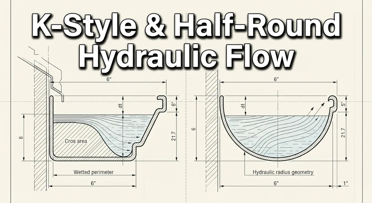
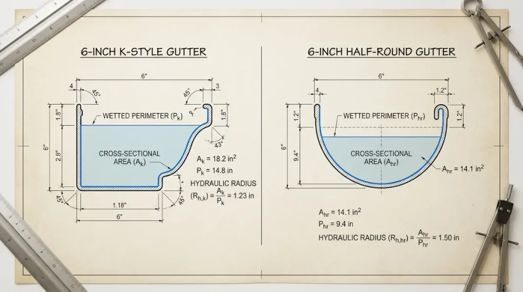
The K-style gutter profile features a flat bottom, near-vertical back wall, and an ogee-curved front face. This geometry produces a cross-sectional shape that is approximately trapezoidal — wide at the top, with a flat carrying floor. The flat bottom maximizes cross-sectional area relative to the nominal width designation. The near-vertical back wall minimizes the wetted perimeter on the rear contact surface. The result is a favorable hydraulic radius for a fabricated sheet metal profile — the K-style carries more water per inch of nominal width than its half-round counterpart at equivalent pitch.
The Half-Round Profile
The half-round gutter profile is a true semicircle. Its geometry is mathematically clean and historically proven — half-round copper systems have managed roof drainage on significant structures for well over a century. However, the semicircular profile produces a wetted perimeter that is proportionally longer relative to its cross-sectional area than the K-style profile at the same nominal width. The curved interior surface contacts more of the water column across the full fill height, generating more friction drag per unit of cross-sectional area. The hydraulic radius of a half-round profile is lower than that of an equivalent-width K-style profile, and the GPM flow capacity reflects that difference directly.
Precise Cross-Sectional Area & Flow Capacity Comparison Data
The following reference data reflects calculated cross-sectional areas, hydraulic radius values, and estimated GPM flow capacities at a standard residential pitch of 1/16 inch drop per linear foot — the minimum functional pitch for a residential guttering run. GPM values are derived from Manning’s equation for open-channel flow using a roughness coefficient of n = 0.011 for smooth-formed aluminum and copper profiles. For current IRC and IBC drainage sizing code references, consult the official building code documentation maintained at ICCsafe.org.
| Profile Type | Nominal Width | Cross-Sectional Area (in²) | Wetted Perimeter (in) | Hydraulic Radius (in) | Est. Flow Capacity (GPM) |
|---|---|---|---|---|---|
| K-Style | 4 inch | 5.26 | 7.72 | 0.68 | 38 GPM |
| Half-Round | 4 inch | 6.28 | 6.28 | 1.00 | 46 GPM |
| K-Style | 5 inch | 7.96 | 9.12 | 0.87 | 63 GPM |
| Half-Round | 5 inch | 9.82 | 7.85 | 1.25 | 76 GPM |
| K-Style | 6 inch | 11.77 | 11.15 | 1.06 | 102 GPM |
| Half-Round | 6 inch | 14.14 | 9.42 | 1.50 | 127 GPM |
Critical specification note: At the 6-inch nominal size, the half-round profile carries approximately 25% more flow volume than the K-style profile at equivalent pitch. This differential inverts the common field assumption that K-style gutters universally outperform half-round profiles on high-load rooflines. The K-style advantage is cross-sectional area efficiency relative to fascia projection depth — not raw hydraulic throughput. Where fascia depth is not a constraint and the roofline geometry permits correct pitch, a properly sized half-round system will outperform a K-style system of equivalent nominal width on a GPM-per-inch-of-width basis.
Practical Specification Implications
When K-Style Is the Correct Specification
- Standard production residential construction where fascia board depth is limited and the flat-back K-style profile mounts flush without projection
- High-volume seamless aluminum installations where machine-formed K-style profile is the production standard and field-fabricated half-round is not operationally practical
- Rooflines with moderate drainage loads where the cross-sectional area advantage of K-style at smaller nominal sizes (4-inch and 5-inch) is sufficient for the calculated GPM demand
- Budget-constrained projects where the material and labor cost differential between K-style and half-round copper or steel represents a disqualifying factor
When Half-Round Is the Correct Specification
- Historical restoration work on structures originally equipped with half-round copper or galvanized steel systems, where profile authenticity is a preservation requirement
- High-end residential new construction specifying copper or zinc half-round systems where long-term durability and material performance are primary selection criteria
- Rooflines with high valley-concentrated discharge points where the superior hydraulic radius of the half-round profile provides measurable GPM headroom over K-style at equivalent nominal width
- Architectural specifications requiring a round-bottom trough profile for aesthetic or structural reasons — round-bottom profiles also shed debris more cleanly than flat-bottom K-style troughs under low-flow conditions
Outlet Sizing Interaction
Profile geometry does not operate in isolation from outlet sizing. A half-round trough with a superior hydraulic radius is still capacity-limited by the outlet diameter and the outlet’s placement relative to the hydraulic center of the run. A 6-inch half-round trough feeding a 2-inch round outlet is not delivering 127 GPM to the downspout — it is delivering whatever the outlet diameter and inlet geometry will pass, which is substantially less. Outlet sizing must be calculated as a separate variable from trough profile selection. The trough profile determines the maximum hydraulic capacity of the collection system. The outlet diameter and placement determine how much of that capacity is actually transferred to the downspout run. Both calculations are required for a complete drainage system specification.
For complete project layouts, custom estimation tools, and full tool rig recommendations backed by 31 years of trade experience, consult our comprehensive guttering tools resource center.
1 thought on “K-Style & Half-Round Hydraulic Flow: Cross-Sectional Capacity Reference”