
Downspout Sizing & Regional Rainfall Intensity: IRC Calculation Reference
The most consistent installation error in residential guttering work is not a pitch problem or a sealant failure — it is an undersized downspout specified by visual habit rather than calculated drainage load. The standard field practice of placing one 2×3 downspout per 30 to 40 feet of gutter run produces correct results on simple rooflines in moderate-rainfall regions.
It produces chronic overflow, fascia saturation, and foundation discharge failures on complex multi-story rooflines, valley-concentrated discharge points, and any installation located in a regional rainfall intensity zone above 3.5 inches per hour.
Downspout sizing & regional rainfall intensity are not independent variables — they are directly linked through a calculable mathematical relationship that the International Residential Code documents in precise, enforceable terms. This reference provides that calculation framework in full, with exact figures for the scenarios where standard 2×3 sizing fails and 3×4 specification becomes structurally mandatory.
The IRC Baseline: Downspout Sizing by Roof Area and Rainfall Intensity
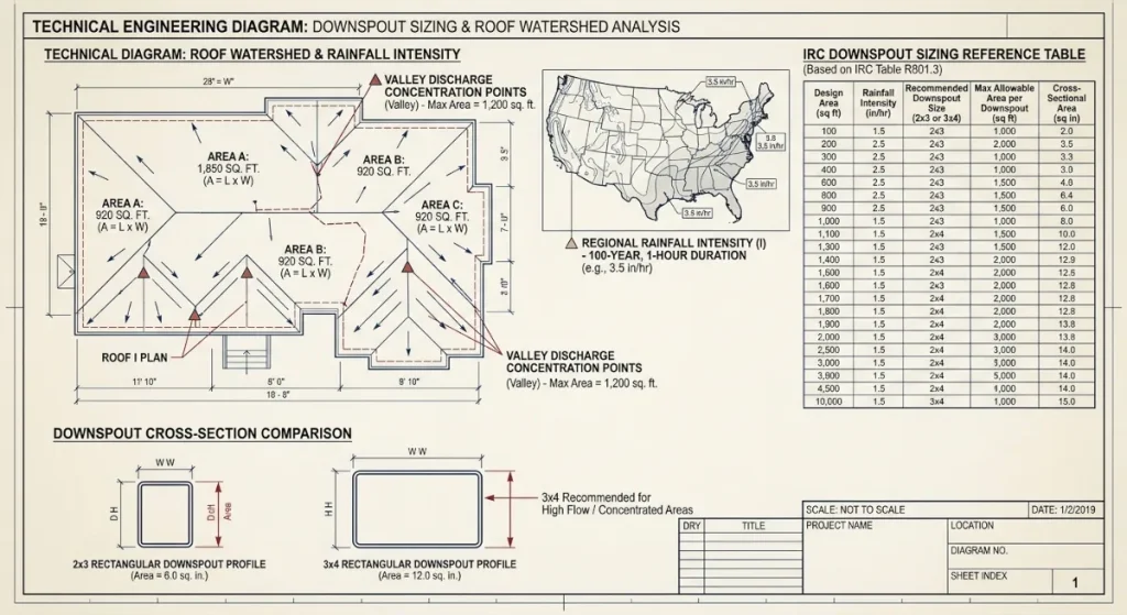
The International Residential Code establishes the foundational sizing relationship for residential roof drainage systems. The IRC baseline standard is 1 square inch of downspout cross-sectional area per 1,200 square feet of adjusted roof area at a regional rainfall intensity of 1 inch per hour. That ratio is the starting point — not the final answer.
It scales proportionally with regional intensity, and it applies to the adjusted roof area after pitch multiplier factors have been applied, not to the raw horizontal footprint of the building.
The scaling relationship is linear and direct. At 2 inches per hour regional intensity, the same roof area requires twice the downspout cross-section. At 4 inches per hour — a standard design storm intensity across most of the southeastern United States — it requires four times the cross-section that the 1-inch-per-hour baseline produces.
Applying the 1-inch-per-hour baseline to a southeastern installation without intensity correction is not a conservative approximation. It is a specification that will fail under the first significant storm event of the season.
The Intensity-Adjusted Sizing Formula
The correct downspout cross-section requirement for any installation is calculated as follows:
- Step 1 — Establish adjusted roof area (A): Multiply the horizontal projected area of the roof plane draining to the outlet by the applicable pitch multiplier factor. Standard pitch multipliers range from 1.00 at flat to 3:12 slope through 1.30 at 12:12 or steeper. A 1,000 square foot horizontal projection at 8:12 pitch produces an adjusted area of 1,100 square feet.
- Step 2 — Identify regional intensity (I): Pull the 100-year, 5-minute recurrence interval intensity value for the project location from NOAA Atlas 14 published data. Do not use annual average rainfall figures — the design storm intensity is the only value relevant to peak drainage load calculation.
- Step 3 — Calculate required cross-section: Divide the adjusted roof area by 1,200, then multiply by the regional intensity value. The result is the minimum required downspout cross-sectional area in square inches for that outlet point.
Worked example — moderate intensity region: Adjusted roof area of 1,100 square feet, regional intensity of 2.5 inches per hour. Required cross-section = (1,100 ÷ 1,200) × 2.5 = 2.29 square inches. A standard 2×3 rectangular downspout provides 6.0 square inches of cross-section — adequate for this load with significant margin.
Worked example — high intensity region: Adjusted roof area of 1,100 square feet, regional intensity of 4.8 inches per hour (Houston, TX design storm baseline). Required cross-section = (1,100 ÷ 1,200) × 4.8 = 4.40 square inches. A standard 2×3 downspout at 6.0 square inches still passes — but at 73% of capacity before any valley concentration factor is applied. Add a valley discharge point to this outlet and the 2×3 profile surcharges immediately.
Standard Downspout Profiles: Cross-Sectional Area Reference
Downspout selection requires matching the calculated minimum cross-section requirement against the actual interior flow area of the available profiles. Nominal downspout dimensions are exterior measurements — interior flow area is the operative figure for drainage load calculations.
| Profile Type | Nominal Dimensions | Interior Cross-Section (in²) | Max Adjusted Roof Area at 1 in/hr (sq ft) | Max Adjusted Roof Area at 4 in/hr (sq ft) |
|---|---|---|---|---|
| Round | 2-inch diameter | 3.14 | 3,768 | 942 |
| Round | 3-inch diameter | 7.07 | 8,484 | 2,121 |
| Rectangular | 2×3 inch | 6.00 | 7,200 | 1,800 |
| Rectangular | 3×4 inch | 12.00 | 14,400 | 3,600 |
| Rectangular | 4×5 inch | 20.00 | 24,000 | 6,000 |
Critical read on this table: At a 4-inch-per-hour regional intensity — which covers the majority of the southeastern U.S. including Tennessee, Alabama, Georgia, Mississippi, Louisiana, and coastal Florida — a standard 2×3 downspout handles a maximum adjusted roof area of only 1,800 square feet per outlet before the cross-section is fully consumed.
Any installation in this intensity band with outlet watershed areas exceeding 1,800 square feet requires either a 3×4 profile or multiple 2×3 outlets serving the same drainage zone.
Valley Discharge Concentration: When Standard Sizing Fails
A roof valley is a hydraulic amplifier. Where two roof planes intersect and drain toward a common low point, the discharge volume arriving at the valley terminus is not the sum of two equal flows — it is a concentrated, high-velocity stream that arrives faster and in greater volume than either roof plane would produce independently.
On multi-story residential rooflines with intersecting ridgelines, that concentration effect can multiply the effective drainage load at a single outlet point by a factor of 2.0 to 3.5 over what the raw watershed area calculation would suggest.
Valley Concentration Factor Application
The valley concentration factor (VCF) is applied as a multiplier to the adjusted roof area of the valley-fed drainage zone before the intensity-adjusted cross-section calculation is run. The appropriate VCF depends on the valley geometry, the combined pitch of the intersecting planes, and the length of the valley run feeding the outlet point.
- Shallow valley (combined pitch below 6:12, valley run under 20 feet): VCF = 1.5 — apply 1.5× multiplier to adjusted roof area before calculating required cross-section
- Standard valley (combined pitch 6:12 to 9:12, valley run 20 to 35 feet): VCF = 2.0 — the outlet at this valley terminus is receiving the hydraulic equivalent of twice the raw watershed area in peak flow volume
- Deep valley (combined pitch above 9:12, valley run exceeding 35 feet): VCF = 2.5 to 3.5 — this is the configuration that renders 2×3 downspouts structurally inadequate regardless of the individual roof plane watershed areas
Worked Valley Example: Why 2×3 Fails at Complex Intersections
A two-story residential roofline with intersecting ridgelines. Each roof plane has an adjusted watershed area of 800 square feet. Combined adjusted area at the valley outlet: 1,600 square feet. Regional intensity: 4.2 inches per hour (standard for Knoxville, TN and surrounding East Tennessee market). Valley run length: 28 feet at a combined pitch of 8:12. VCF = 2.0.
- Effective drainage area after VCF: 1,600 × 2.0 = 3,200 square feet
- Required cross-section: (3,200 ÷ 1,200) × 4.2 = 11.20 square inches
- 2×3 downspout capacity: 6.00 square inches — deficit of 5.20 square inches — fails
- 3×4 downspout capacity: 12.00 square inches — surplus of 0.80 square inches — passes at minimum
- Correct specification: Single 3×4 smooth-wall downspout, or dual 2×3 outlets if the architectural layout permits splitting the valley discharge across two separate downspout runs
This is not an edge case. This is a standard two-story residential intersection in a moderate-to-high regional intensity zone. The 2×3 downspout fails this calculation by nearly double the required cross-section. The failure is not visible on installation day — it appears as chronic overflow at the valley outlet during the first heavy regional storm of the season.
Smooth-Wall vs. Corrugated Pipe: Flow Efficiency at the Discharge Run
Downspout profile selection does not end at the outlet connection. The discharge run from the downspout base to the final discharge point introduces additional friction loss that reduces effective flow capacity below the cross-section figures in the sizing table above. Corrugated flexible discharge pipe — commonly used for underground extensions — introduces significantly higher friction loss than smooth-wall rigid pipe of equivalent diameter due to its ribbed interior surface geometry.
- Smooth-wall aluminum or PVC downspout pipe: Manning’s roughness coefficient n = 0.011 — minimal friction loss, flow capacity closely matches cross-section sizing table values
- Corrugated flexible discharge pipe: Manning’s roughness coefficient n = 0.024 or higher — friction loss reduces effective flow capacity by 30% to 45% compared to smooth-wall pipe of equivalent cross-section
On high-intensity regional installations or valley-concentrated outlet points where the downspout cross-section has been sized to minimum tolerance, substituting corrugated flexible pipe for smooth-wall at the discharge run eliminates the hydraulic margin the calculation was designed to preserve.
Smooth-wall rigid pipe is the correct specification at any discharge run serving a 3×4 or larger outlet on a high-intensity or valley-concentration installation.
For current IRC code references governing downspout cross-section minimums, discharge placement requirements, and underground extension standards applicable to residential drainage systems, consult the official building code documentation at ICCsafe.org.
While maximizing vertical downspout dimensions and cross-sectional drainage areas ensures your system can safely exhaust localized water volume, your downspouts will remain entirely starved of water if the horizontal channels lack proper gravitational velocity.
To ensure your system moves water toward these vertical escape points at an engineered rate, consult our detailed guide on Drainage & Slope Calculations to lock in the exact pitch per linear foot required for your roofline footprint.
For complete project layouts, custom estimation tools, and full tool rig recommendations backed by 31 years of trade experience, consult our comprehensive resource center.
1 thought on “Downspout Sizing & Regional Rainfall Intensity: Field Manual”