
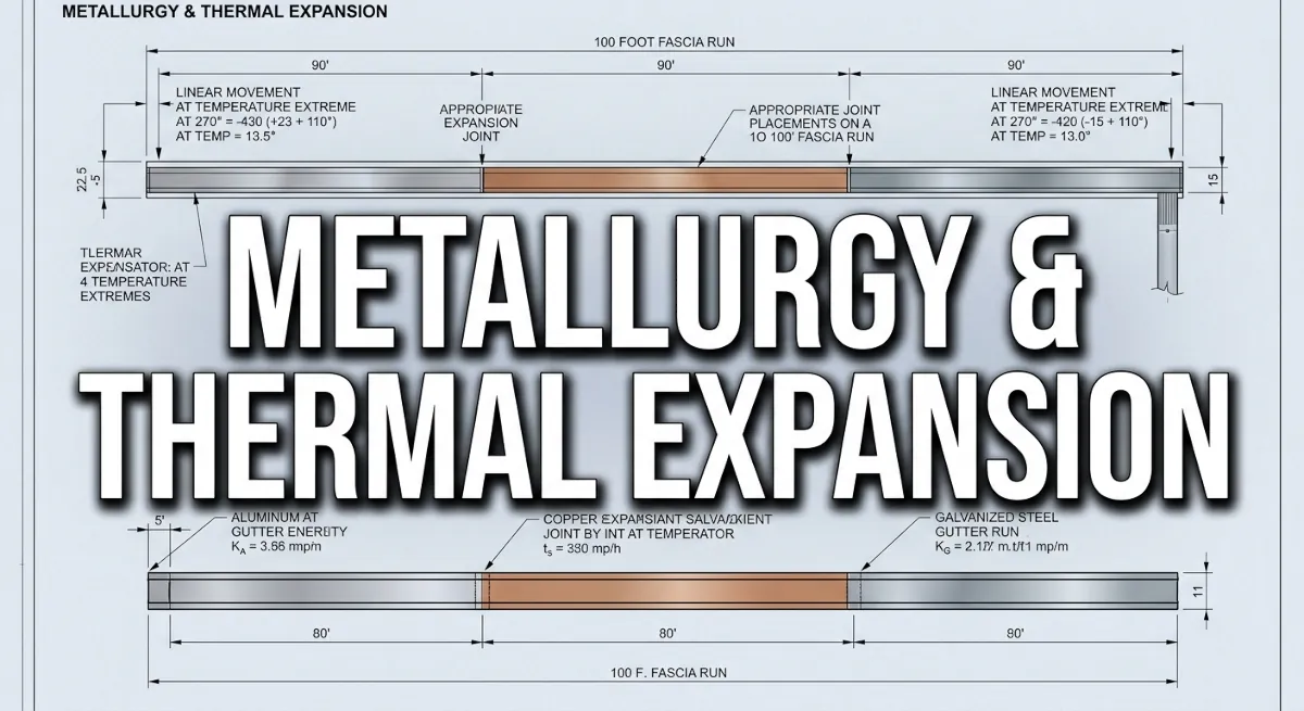
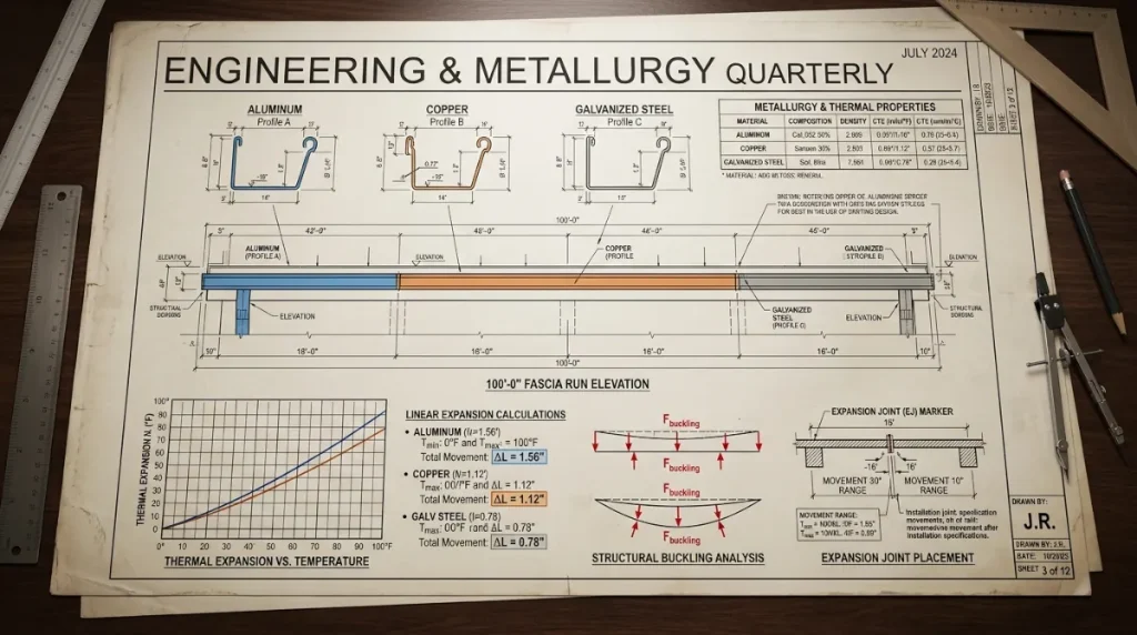
Metallurgy & Thermal Expansion: Architectural Gutter Metal Coefficient Reference
Metal moves. Every contractor working in the exterior envelope understands this at a general level — but the ones who build drainage systems that last 30 years understand it at a coefficient level. The gap between those two positions is exactly where chronic joint failures, torn fastener anchors, buckled trough sections, and pulled end caps originate.
Metallurgy & thermal expansion is not an abstract engineering concept for residential guttering work — it is the primary mechanical force acting on every long gutter run through every seasonal temperature cycle, and it must be designed for explicitly before the first hanger is set.
This reference documents the precise linear expansion coefficients for aluminum, copper, and galvanized steel, calculates the actual movement figures on extended runs under documented regional temperature swings, and establishes the expansion joint placement standards required to keep those forces from destroying the system over time.
Linear Thermal Expansion Coefficients: Material Reference Data
The linear coefficient of thermal expansion (CTE) expresses how much a material expands or contracts per unit of length for each degree of temperature change. For guttering applications, the relevant unit is inches of movement per inch of run per degree Fahrenheit. These are fixed material properties — they do not vary by manufacturer, gauge, or profile geometry. They are determined entirely by the alloy composition of the metal.
| Material | Alloy / Grade | CTE (in/in/°F) | CTE (in/in/°C) | Relative Expansion Rate |
|---|---|---|---|---|
| Aluminum | 3105-H25 (standard seamless gutter alloy) | 0.0000128 | 0.0000231 | Highest of the three |
| Copper | C11000 (electrolytic tough pitch) | 0.0000094 | 0.0000170 | Mid-range |
| Galvanized Steel | G90 hot-dip galvanized sheet | 0.0000065 | 0.0000117 | Lowest of the three |
Material selection note: Aluminum expands at nearly twice the rate of galvanized steel and 36% faster than copper under identical temperature conditions.
This differential is the primary reason that aluminum guttering systems — which dominate residential production installation — require more aggressive expansion joint planning than copper or steel systems of equivalent run length.
The material is cost-effective, lightweight, and corrosion-resistant, but its thermal expansion behavior demands respect at the specification stage.
Calculated Linear Movement: 100-Foot Run Analysis by Material and Temperature Swing
The linear movement formula is straightforward: ΔL = L × CTE × ΔT, where ΔL is the total linear movement in inches, L is the run length in inches, CTE is the material coefficient, and ΔT is the temperature differential in degrees Fahrenheit between the installation baseline and the seasonal extreme being calculated.
The following calculations use a 100-foot run (1,200 inches) as the baseline, with three regional temperature swing scenarios representing the range of conditions encountered across the continental United States:
Scenario A — Moderate Climate (60°F Seasonal Swing)
Representative of coastal Pacific Northwest, mild mid-Atlantic, and lower elevation southeastern installations where winter lows rarely drop below 20°F and summer peaks stay below 90°F surface temperature on metal.
- Aluminum (3105-H25): 1,200 × 0.0000128 × 60 = 0.922 inches of movement
- Copper (C11000): 1,200 × 0.0000094 × 60 = 0.677 inches of movement
- Galvanized Steel (G90): 1,200 × 0.0000065 × 60 = 0.468 inches of movement
Scenario B — Continental Climate (100°F Seasonal Swing)
Representative of the upper Midwest, Great Plains, interior Southeast, and mid-Atlantic regions where summer metal surface temperatures reach 140°F to 160°F under direct sun exposure and winter lows drop to 0°F to 20°F. This is the design condition for the majority of the continental U.S. residential guttering market.
- Aluminum (3105-H25): 1,200 × 0.0000128 × 100 = 1.536 inches of movement
- Copper (C11000): 1,200 × 0.0000094 × 100 = 1.128 inches of movement
- Galvanized Steel (G90): 1,200 × 0.0000065 × 100 = 0.780 inches of movement
Scenario C — Extreme Climate (140°F Seasonal Swing)
Representative of high-altitude Rocky Mountain installations, upper Great Plains freeze-thaw zones, and any installation where metal surface temperatures reach 160°F or higher under summer sun exposure — a documented condition on south-facing dark-metal gutter runs in direct solar exposure — combined with winter lows at or below -20°F.
- Aluminum (3105-H25): 1,200 × 0.0000128 × 140 = 2.150 inches of movement
- Copper (C11000): 1,200 × 0.0000094 × 140 = 1.579 inches of movement
- Galvanized Steel (G90): 1,200 × 0.0000065 × 140 = 1.092 inches of movement
Critical field interpretation: A 100-foot aluminum run in a continental climate moves over 1.5 inches between its coldest contracted state and its hottest expanded state. That 1.5 inches of linear displacement must go somewhere.
If the system has no designed accommodation for that movement, it goes into the weakest mechanical connection in the run — and it will find that connection reliably, every season, until the connection fails.
Structural Failure Mechanics: What Unmanaged Thermal Movement Does to a Gutter System
Fastener Anchor Pullout
Hidden hanger systems screw directly through the gutter trough back into the fascia board. On a fixed-anchor system with no expansion accommodation, thermal expansion forces the trough to push and pull against every fastener in the run simultaneously.
The cumulative force of 1.5 inches of aluminum movement distributed across a 100-foot run does not distribute evenly — it concentrates at the fixed endpoints and at any hanger that has slightly more friction resistance than its neighbors.
Those high-resistance hangers experience repeated cyclical loading in both tension and shear. Over three to five seasonal cycles, the screw hole in the fascia board elongates, the hanger pulls partially free, and the trough begins to sag at that location. The sag reverses the pitch. Standing water accumulates. The failure accelerates.
Joint Separation and Sealant Failure
Sectional gutter systems with field-applied silicone sealant at lap joints are particularly vulnerable to thermal cycling. Silicone sealant has a finite elongation tolerance — typically 25% to 50% of the joint gap width depending on the product specification.
On a long run without expansion joints, the full thermal movement of the run is transferred to every sealed joint in the system. Joints near the endpoints of a fixed run experience the greatest displacement.
Once the sealant elongation limit is exceeded — which occurs progressively over multiple seasonal cycles rather than in a single event — the seal cracks, water infiltrates the joint, and the fascia behind it begins to absorb moisture. The external symptom is a drip at a lap joint during rainfall. The structural consequence is fascia rot that extends well beyond the visible leak point.
Trough Buckling
On runs where both endpoints are rigidly fixed — a common condition when end caps are pop-riveted to a rigid corner assembly at each end of the run — thermal expansion has no linear escape path. The expanding metal resolves the compressive force by deforming laterally.
The trough buckles outward at its midpoint or at the weakest cross-section in the run. In aluminum, this produces a visible bow in the front face of the trough. In copper, the higher yield strength resists buckling longer but stores more elastic energy — when it does yield, the deformation is more severe and less reversible than in aluminum.
Expansion Joint Placement Standards: Designing for Movement
The engineering solution to thermal expansion in long gutter runs is a designed slip point — an expansion joint that allows the trough sections on either side of it to move independently without transferring force to the fastener anchors, sealed joints, or end connections. The expansion joint absorbs the linear movement that the calculation demands must go somewhere, and it directs that movement to a location designed to handle it.
Maximum Interval Between Expansion Joints
- Aluminum in continental and extreme climate zones: Expansion joint required at a maximum interval of 40 feet — this limits the maximum thermal movement at any single joint to approximately 0.61 inches at a 100°F swing, within the functional range of standard slip-joint designs
- Aluminum in moderate climate zones: Expansion joint required at a maximum interval of 50 feet — the reduced temperature swing keeps per-joint movement below 0.46 inches at the 50-foot interval
- Copper in continental climate zones: Expansion joint required at a maximum interval of 50 feet — lower CTE reduces per-foot movement, but the higher material cost of copper makes joint failure a more consequential event, justifying conservative interval specification
- Galvanized steel in any climate zone: Expansion joint required at a maximum interval of 60 feet — the lowest CTE of the three materials provides the most movement tolerance per linear foot of run
Expansion Joint Construction and Placement Logic
- Slip-sleeve joint design: A section of gutter profile cut to 6 to 8 inches in length, slightly oversized to sleeve over the trough ends on both sides of the joint gap, sealed on one side only — allowing the unsealed side to slide freely through the thermal cycle without transferring force to the sealed connection
- Joint gap sizing: The gap between trough ends at the expansion joint should be set at installation to the mid-point of the expected thermal movement range — approximately 3/4 of the calculated maximum movement at the joint interval — to allow equal accommodation of both expansion and contraction from the installation temperature baseline
- Placement priority: Expansion joints should be positioned at the hydraulic high point of a run section wherever possible, keeping the joint above the waterline during normal flow conditions and minimizing the risk of water infiltration at the slip interface
- Hanger placement at joints: Install one fixed hanger on each side of the expansion joint within 6 inches of the joint location to prevent trough rotation or lateral displacement at the slip point during thermal cycling
For current ASTM material specifications covering aluminum alloy 3105-H25, copper alloy C11000, and G90 galvanized steel sheet products used in architectural guttering applications — including gauge tolerances, tensile strength minimums, and elongation ratings relevant to thermal cycling performance — consult the official standards documentation maintained at ASTM International at astm.org.
While selecting the correct metal alloys and engineering your system to withstand cyclical thermal expansion movements prevents physical joint failure over time, those durable metal seams will still fail if the system becomes structurally overwhelmed by localized storm volume.
To accurately balance your structural material choices with the hydraulic demands of your specific climate zone, read our technical blueprint on Downspout Sizing & Regional Rainfall Intensity to ensure your drainage channels can exhaust water at a rate that matches your calculated material volume constraints.
While mastering the physics of metal expansion and downspout drainage capacity establishes the theoretical foundation for high-performance roof drainage systems, translating these metrics into the field requires professional-grade equipment.
To explore the precise layout levels, seamless roll-forming hardware, and specialized hand tools necessary to execute these engineering tolerances on a real-world job site, check out our curated guide to the industry’s top guttering tools to properly equip your installation setup.
1 thought on “Metallurgy & Thermal Expansion: Gutter Metal Field Reference”